1x On or ChangeOver tactile switch controlled Relay in CMOS logic
In the times of µControllers CMOS-logic devices almost seem to be forgotten.
But they allow to build simple reliable control circuits often without the need of a another supply rail since they can be supplied with up to 18V.
One can connect them to tactile switches, µControllers and remote control signals. For our demands the simplest devices from the CD4000 series suffice, as for example the CD4013, CD4027 or CD4098.
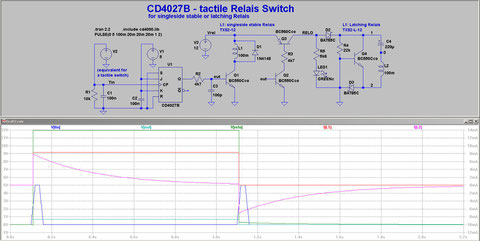
The circuit of fig. 1 utilizes a CD4027B, a CMO-logic containing two independent J-K FlipFlops. Here only one half is shown. A FlipFlop changes its output level whith every touch of the tactile switch (Tin). It can steer transistors connected to its oututs which than can supply relais with sufficient coil current.
Functioning:
On energizing the circuit the gnd connected (low) Set- and Reset-inputs (S and R) pull the Q output low and Q high.
If the inputs J and K are also connected to gnd then every positive pulse at input CP swithces the outputs to the other level.
R1 and C1 ground the input CP of the FlipFlop. C1 functions as a debouncer against mechanical switch bounce, so that IC1 can surely detect a touch.
On pressing the switch a short positive pulse triggers input CP and output Q switches high and Q low. R2 steers the basis of the following NPN-transistor, C3 ´softens´ the steep pulse slightly.
If one wants to use a single side stable relais (L1, eg a Panasonic TXS2-12), just connect the relais from the collector of Q1 to the positive supply rail.
Diode D1 protects the relais from voltage peaks when it switches off.
Single side stable relais require a continued energizing coil current. Latching relais on the other hand only require short pulsed current to switch over. This feature makes them specially interesting for audio useage, as there flows no coil current while active. It requires a bit more circuitry though.
They come in 2 flavours, 1 coil latching and 2 coil latching.
The 1coil latching features one energizing coil. To switch over the polarity of the current pulses must be of opposite polarity.
The difference of the 2 coil latching relais is that it features two independant coils.
So differ the pulsser-circuits. Here I describe the pulser for a 1 coil latching relais type. In earlier days You could buy specialized ICs for this task, but today one needs to build discrete again.
When the switching transistor Q2 opens up then the PNP-transistor Q3 switches on the supply rail (RELO) for the relais-pulser circuit.
Fed via R5 the LED1 lits, marking the switching status.
At switch-on the circuit comprised of D2, D3, R4, Q4 and C4 generates a short current pulse that triggers the relais L2 (eg a Panasonic TXS2-L-12). On switch-off the circuit generates another current pulse but of opposite polarity that switches the relais off.
The value of C4 defines the width and height of the currrent pulse hence the energy of the pulse. It´s value may be changed according to the specifications of the relais.
In fig.1 the supply rail of the CD4027B is 5V and for he relais its 12V. Since the CMOS-logic allows for a wide range of supply voltage of ~4-18V and the relais come in different voltage classes too, the circuit can be supplied from different voltages or the same rail. In case of a common 12V supply R2 should b changed to 10kΩ.
As a final remark it should be noted that the CD4027B can of course control two relais independently. If not used the open pins of the second logic of the device should be connected to gnd.